



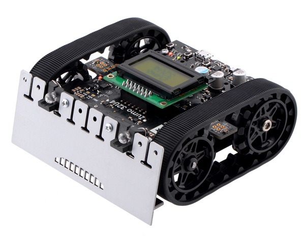

The Pololu Zumo 32U4 robot is a versatile tracked robot based on the Arduino-compatible ATmega32U4 MCU. It includes two 75:1 HP micro metal gearmotors along with integrated dual motor drivers, an LCD, quadrature encoders, line sensors, side and front proximity sensors for detecting objects, and a full IMU for detecting impacts and tracking orientation. The low-profile robot is less than 10 cm × 10 cm—small enough to qualify for Mini Sumo. No soldering or assembly is required; just add 4 AA batteries and a USB cable and your Zumo is ready for programming.
Overview
The Zumo 32U4 is a highly integrated, user-programmable and customizable tracked robot. It measures less than 10 cm on each side and weighs approximately 275 g with batteries (170 g without), so it is both small enough and light enough to qualify for Mini-Sumo competitions, but its versatility makes it capable of much more than just robot sumo battles.
At the heart of the Zumo 32U4 is an ATmega32U4 AVR microcontroller from Microchip (formerly Atmel), and like our A-Star 32U4 programmable controllers, the Zumo 32U4 features a USB interface and ships preloaded with an Arduino-compatible bootloader. A software add-on is available that makes it easy to program the robot from the Arduino environment, and we have Arduino libraries and example sketches to help get you started. A USB A to Micro-B cable (not included) is required for programming. For advanced users who want to customize or enhance their robots with additional peripherals, the robot’s power rails and microcontroller’s I/O lines can be accessed via 0.1″-spaced through-holes along the sides and front of the main board.
|
|
|
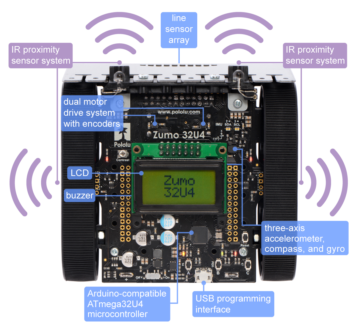
The Zumo 32U4 features two H-bridge motor drivers and a variety of integrated sensors, including a pair of quadrature encoders for closed-loop motor control, a complete inertial measurement unit (3-axis accelerometer, gyro, and magnetometer), five downward-facing reflectance sensors for line-following or edge-detection, and front- and side-facing proximity sensors for obstacle detection and ranging. Three on-board pushbuttons offer a convenient interface for user input, and an LCD, buzzer, and indicator LEDs allow the robot to provide feedback.
 |
The Zumo 32U4 robot is available fully assembled with three different motor options (see the Motors section below for more information on how these different gear ratios perform):
- Assembled with 50:1 HP motors — highest speed and lowest torque of the three options
- Assembled with 75:1 HP motors — average speed and torque
- Assembled with 100:1 HP motors — highest torque and lowest speed
The Zumo 32U4 robot is also available as a kit (without motors) for those who would prefer to assemble it themselves or who want to use different motors than those in the three assembled versions.
Details for item #3126
This version of the Zumo 32U4 robot (item #3126) ships fully assembled with a pair of 75:1 HP micro metal gearmotors (with extended motor shafts). As described above, two other assembled versions are also available, one with a higher gear ratio that is slower but can deliver more torque and one with a lower gear ratio that is faster but delivers less torque.
You can use the following table to compare these three gear ratios in more detail. The first four columns are specifications of the motors themselves, while the last column is the measured top speed of a Zumo chassis loaded to a weight of 500 g and driven with these motors. Note that the specifications are for 6V operation, which is approximately the voltage you would get with four alkaline batteries; four NiMH AA cells will typically provide less than 5V.
| Micro Metal Gearmotor |
Free-Run Speed @ 6V |
Stall Torque @ 6V |
Stall Current @ 6V |
Top Zumo Speed @ 6V and 500g |
|
|---|---|---|---|---|---|
| 50:1 HP or 50:1 HPCB | 625 RPM | 15 oz·in | 1600 mA | 40 in/s | (100 cm/s) |
| 75:1 HP or 75:1 HPCB | 400 RPM | 22 oz·in | 1600 mA | 25 in/s | (65 cm/s) |
| 100:1 HP or 100:1 HPCB | 320 RPM | 30 oz·in | 1600 mA | 20 in/s | (50 cm/s) |
 |
Batteries (not included)
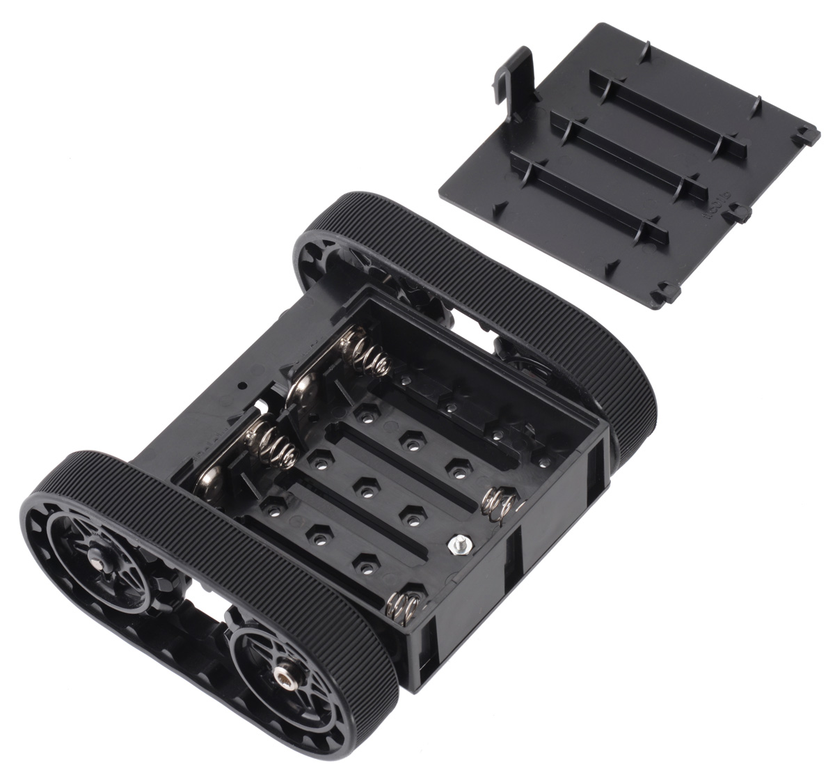
The Zumo 32U4 robot runs off of four AA batteries. It works with both alkaline and NiMH batteries, though we recommend using rechargeable AA NiMH cells.
Optional accessories
- Even more sensors
- Connectors (headers, jumper wires, etc) for adding those sensors or other peripherals
- Tools (soldering iron, diagonal cutters, pliers, screwdrivers, etc) to help with kit assembly
- Replacement sprockets in red or white. The Zumo 32U4 robot includes the black sprockets shown in the left picture below, but other colors can be purchased separately if you want to add a bit of personalization to your robot.
|
|
|
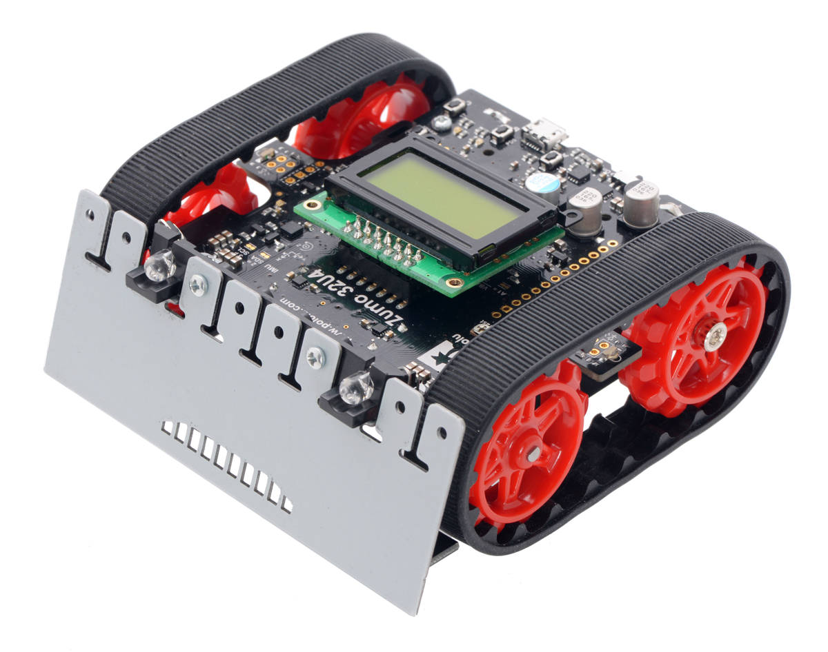
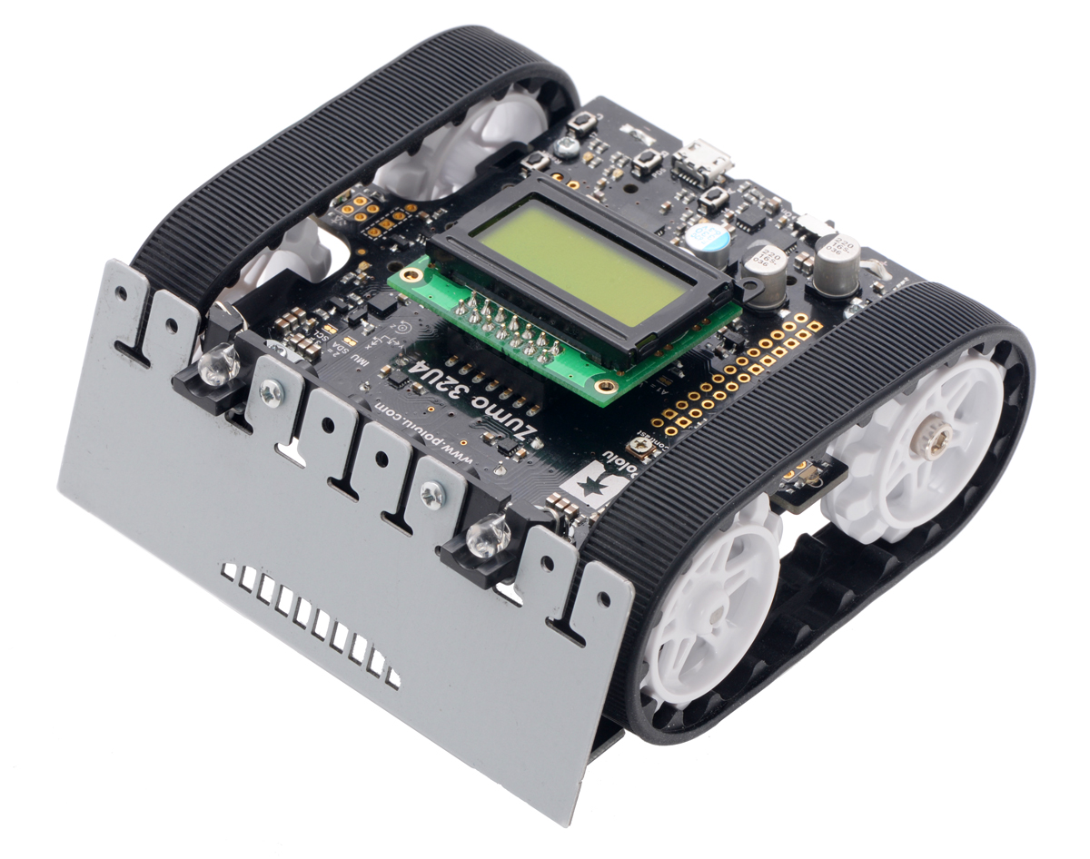
Comparison with the Zumo robot kit for Arduino (with Zumo Shield)
Our older Zumo robot for Arduino, built with a Zumo Shield, is another Arduino-compatible robotic platform based on the Zumo chassis. The Zumo Shield mounts to the Zumo chassis and features motor drivers and various sensors, but it does not have an integrated microcontroller; rather, it is designed to interface with boards that have a standard Arduino form factor, like an Arduino Uno, Arduino Leonardo, or A-Star 32U4 Prime, and these boards serve as the main controller for the robot.
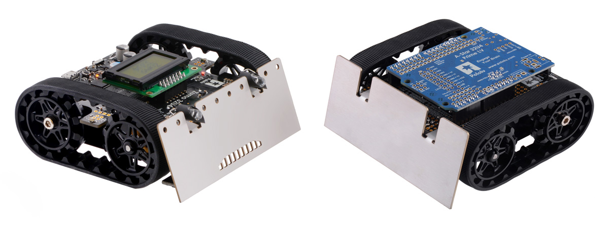 |
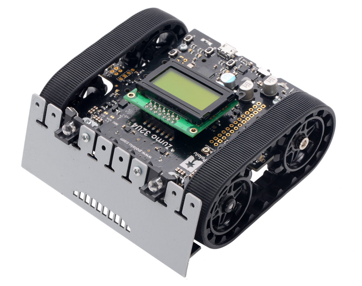
| A Zumo 32U4 robot (left) and a Zumo robot for Arduino with an A-Star 32U4 Prime LV (right). |
|---|
By contrast, the Zumo 32U4 includes an on-board ATmega32U4 microcontroller (the same one used in the Leonardo and A-Star 32U4 boards), combining the functions of the Zumo Shield and the separate Arduino controller into a single, compact board that is just as easy to program as a standard Arduino or A-Star thanks to its USB interface and preloaded Arduino-compatible bootloader. The Zumo 32U4 retains all the features of the Zumo shield (e.g. dual motor drivers, inertial sensors, and buzzer) while adding many new features, including dual quadrature encoders, proximity sensors, an LCD, and two extra user pushbuttons.
Some of the pin mappings and software libraries differ between the Zumo 32U4 and Zumo robot for Arduino, so programs written for one robot generally need to be modified to work on the other.
General specifications
| Version: | assembled with 75:1 HP motors |
|---|
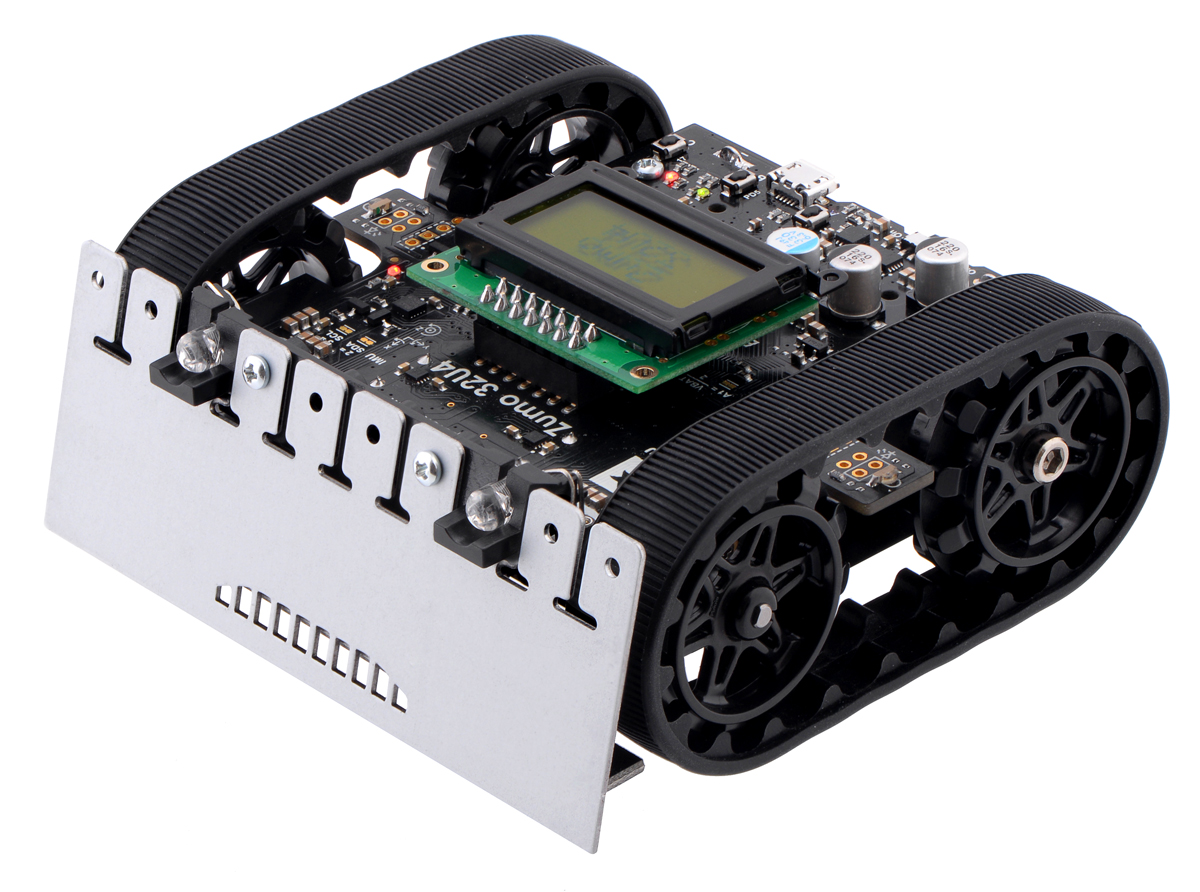 |
| Assembled Zumo 32U4 robot. |
|---|
|
| Main features of the Zumo 32U4 robot. |
|---|
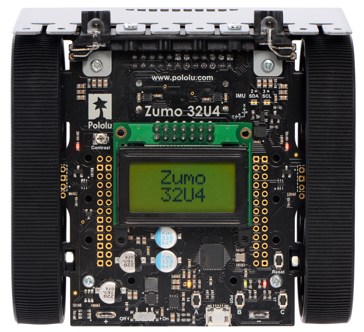 |
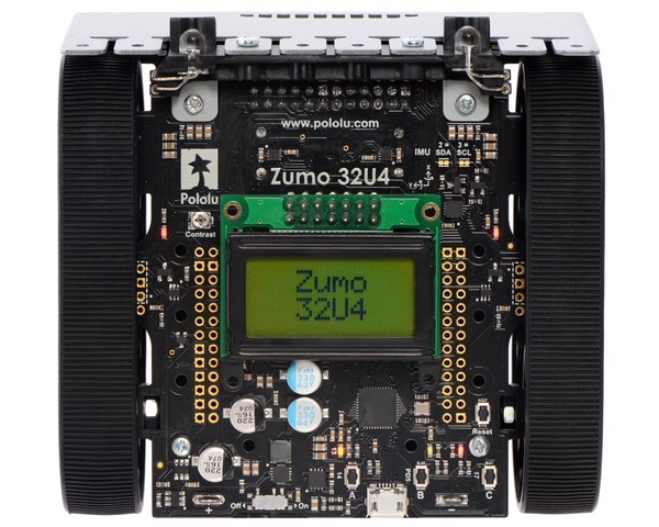
| Assembled Zumo 32U4 robot, top view. |
|---|
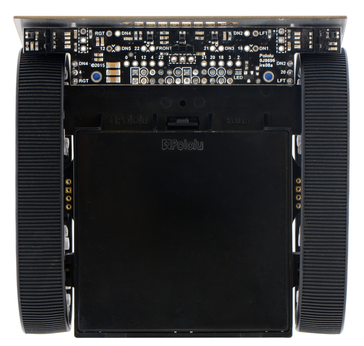 |
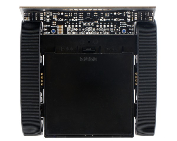
| Assembled Zumo 32U4 robot, bottom view. |
|---|
 |
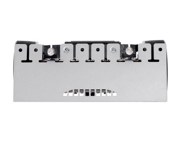
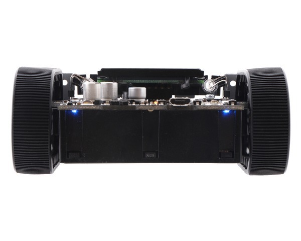
| Assembled Zumo 32U4 robot, front view. |
|---|
 |
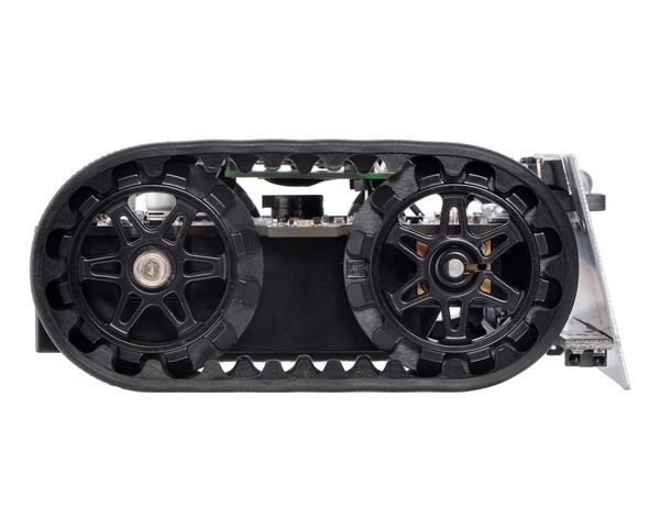
| Assembled Zumo 32U4 robot, side view. |
|---|
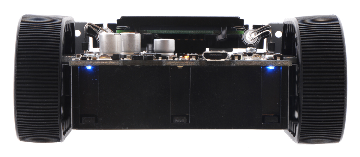 |
| Assembled Zumo 32U4 robot, back view. |
|---|
Documentation and other information
 Pololu Zumo 32U4 Robot User’s Guide (Printable PDF)User’s manual for the Pololu Zumo 32U4 robot.
File downloads
- Pololu A-Star 32U4 drivers for Windows (version 1.3.0.0) (7k zip)
- This download contains the Windows drivers for the A-Star 32U4 and the rest of our 32U4 family of boards.
- Zumo 32U4 pinout diagram (536k pdf)
- Printable pinout diagram of the Zumo 32U4 main board.
- Zumo 32U4 schematic diagram (1MB pdf)
- Printable schematic diagram of the Zumo 32U4 robot.
- 3D model of the assembled Zumo 32U4 Robot (40MB step)
- This model uses simplified models of the control electronics to reduce the file size. More detailed models are available separately of the Zumo 32U4 main board (23MB step) and Zumo 32U4 front sensor array (4MB step).
- Dimension diagram of the Zumo 32U4 Main Board (482k pdf)
- Zumo 32U4 main board drill guide (236k dxf)
- This DXF drawing shows the locations of all of the board’s holes.
- Zumo 32U4 robot 3D model (30MB pdf)
- Rotatable 3D model of an assembled Zumo 32U4 robot (Note: this file might not work properly with all pdf viewers.)
- Texas Instruments DRV8837/DRV8838 motor driver datasheet (1MB pdf)
- LSM303D datasheet (1MB pdf)
- Datasheet for the ST LSM303D 3D accelerometer and 3D magnetometer module.
- L3GD20H datasheet (3MB pdf)
- Datasheet for the ST L3GD20H three-axis digital-output gyroscope.
- Datasheet for the Sharp GP2S60 compact reflective photointerrupter (164k pdf)
- Datasheet for the sensor used on the QTR-3RC and QTR-3A Reflectance Sensor Arrays, the Zumo 32U4 robot front sensor array, and the Optical Encoders for micro metal gearmotors.
- Vishay TSSP77038 IR receiver module datasheet (268k pdf)
- TPS2113A datasheet (1MB pdf)
- Datasheet for the Texas Instruments TPS2113A autoswitching power mux.
Recommended links
- Zumo 32U4 Arduino library
- The Zumo32U4 library for the Arduino IDE helps interface with the on-board hardware on the Zumo 32U4 robot.
- Zumo32U4 library documentation
- A-Star repository on GitHub
- This repository contains Arduino add-on files, Windows drivers, and bootloaders for the A-Star 328PB, A-Star 32U4, and the rest of our 32U4 family of boards.
- ATmega32U4 documentation
- Microchip’s product page for the ATmega32U4 AVR microcontroller, with links to its datasheet, application notes, and other resources.
- Using the L3GD20 gyroscope in control systems
- This is a YouTube playlist by control systems lecturer Brian Douglas that uses the L3GD20 MEMS gyroscope. It describes the fundamentals of the gyro and how to use it for closed and open loop control projects with MATLAB/Simulink and Arduino.
Why are the accelerometer readings from my LSM303D stuck at an incorrect value?
We have noticed that the accelerometer in the LSM303D is particularly sensitive to brown-out conditions. If power is removed and the voltage on the 3.3 V power supply line falls significantly, but is not allowed to drop completely to 0 V, the accelerometer can be put into a bad state. When power is reapplied to the LSM303D, the accelerometer then returns readings on some or all axes that are large values and do not change much or at all. (We have often seen readings like -32760 and 24539.)
To prevent this problem from occurring, the voltage on the 3.3 V line must be allowed to fall to about 0 V when power is removed from the LSM303D. Depending on other loads and the amount of capacitance on the 3.3 V line, it can take up to several seconds for this to happen, meaning that you should avoid interrupting power to the LSM303D for any shorter period, and if such a short interruption does occur, you should remove power again for a longer period to allow the accelerometer to reset properly.
If the voltage takes too long to fall, you can add a resistor between 3.3 V and ground (a “bleeder resistor”) to discharge the 3.3 V line more quickly when power is removed. We suggest trying a resistor in the 1 kΩ to 10 kΩ range. (Note that a stronger bleeder resistor will cause the voltage to fall more quickly when power is removed, but it will also waste more power when the supply is present.)
The Zumo 32U4 includes a bleeder resistor on the 3.3 V line.

There are no reviews yet.