
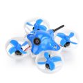


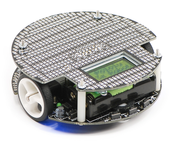
The Pololu 3pi robot is a complete, high-performance mobile platform featuring two micro metal gearmotors, five reflectance sensors, an 8×2 character LCD, a buzzer, and three user pushbuttons, all connected to a C-programmable ATmega328 AVR microcontroller. Capable of speeds exceeding 3 feet per second, 3pi is a great first robot for ambitious beginners and a perfect second robot for those looking to move up from non-programmable or slower beginner robots.
Overview
 |
The 3pi robot is designed to excel in line-following and maze-solving competitions. It has a small size (9.5 cm/3.7″ diameter, 83 g/2.9 oz without batteries) and takes just four AAA cells (not included), while a unique power system runs the motors at a constant 9.25 V independent of the battery charge level. The regulated voltage allows the 3pi to reach speeds up to 100 cm/second while making precise turns and spins that don’t vary with the battery voltage.
The 3pi robot makes a great platform for people with C programming experience to learn robotics, and it is a fun environment for ambitious beginners to learn C programming. At its heart is an ATmega328P AVR microcontroller from Microchip (formerly Atmel) running at 20 MHz and featuring 32 KB of flash program memory, 2 KB RAM, and 1 KB of persistent EEPROM memory. The popular, free GNU C/C++ compiler works perfectly with the 3pi, Atmel Studio provides a comfortable development environment, and an extensive set of libraries provided by Pololu makes it a breeze to interface with all of the integrated hardware. The 3pi is also compatible with the popular Arduino development platform. We provide a number of sample programs to show how to use the various 3pi components, as well as how to perform more complex behaviors such as line following and maze solving.
The diagrams below highlight the important features of the 3pi. Click on either picture for an expanded view.
|
|
For instructions on setting up and programming the 3pi, including sample code, contest ideas, and more, see the 3pi User’s Guide.
Required Accessories
An external AVR ISP programmer, such as our USB AVR programmer v2.1 is required to program the 3pi.
The 3pi is powered by 4 AAA batteries, which are not included. We recommend rechargeable NiMH cells, which may be purchased from Pololu or at a local store carrying electronics. (We also carry a battery charger that works well with these NiMH cells and can be used to charge the batteries while they are still in the robot.)
Optional Accessories
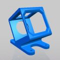
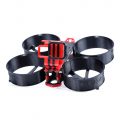
We currently offer three expansion kits for the 3pi that give you room to augment your 3pi with your own custom electronics. Two are basic kits that simply give your 3pi a second level (with prototyping space and key electrical connections to the 3pi base) to which you can add your own electronics. These basic expansion kits are available with black or red solder masks and with or without cutouts. The version with cutouts lets you view the LCD below and allows you to reach the power button, reset button, and ISP programming header on the base. The version without cutouts is a full circle that replaces the LCD, giving you access to more I/O lines and more prototyping space. The pictures below show the black versions of these two basic expansion kits.
|
|

The third option, the m3pi expansion kit, makes it easy to significantly upgrade the capabilities of your 3pi by converting it into an m3pi robot. This expansion board enables the use of ARM’s powerful 32-bit mbed development board as the robot’s high-level controller (mbed has an m3pi library that makes this easy), which offers significantly more processing power and free I/O lines than the 3pi’s built-in 8-bit AVR microcontroller. There are also sockets for Wixel and XBee wireless serial modules, prototyping space for additional sensors and electronics, eight more user-controllable LEDs, and more. If you already have a 3pi robot, you can use the m3pi expansion kit to upgrade it to an m3pi robot. Otherwise, you can get the m3pi robot directly, which includes a 3pi robot connected to a fully-assembled m3pi expansion board (no soldering is required). Please see the m3pi robot product page for more information.
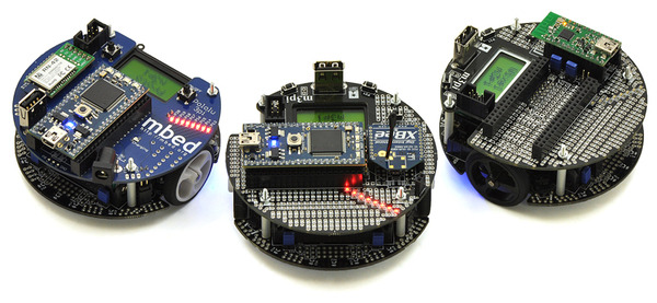 |
| A group of m3pi robots: ARM’s original m3pi (left) and Pololu’s m3pis (center and right). |
|---|
3pi Robot Video Gallery
The following videos from Pololu and our customers show some of the things you can do with the 3pi robot. The first video in the playlist introduces the 3pi’s basic features and operation.
The second video shows a 3pi prototype autonomously solving a line maze, first by exploring the maze and then by running the learned shortest path from start to finish, and the third video shows six 3pi prototypes simultaneously participating in a line-following exhibition at a local robotics competition (last one remaining on the line wins!). Please note the 3pis in the last few videos are using additional hardware for things like RC control and obstacle detection.
The above videos (with descriptions) and more can be found on our 3pi videos page. These videos show many more things that you can do with the 3pi, including RC control, following a laser pointer, wall following, solving looped mazes, and driving around line courses with kinks, gaps, and obstacles. Check out what some of our customers have done with this amazing little robot and get inspired!
|
|
Note: The 3pi robot currently ships with an LCD with a black bezel as shown in the main product picture, not the silver-bezeled LCD shown in some of the product photos and videos.
Dimensions
| Size: | 3.7″ diameter |
|---|
General specifications
| Processor: | ATmega328P |
|---|---|
| Motor driver: | TB6612FNG |
| Motor channels: | 2 |
| User I/O lines: | 21 |
| Minimum operating voltage: | 3 V2 |
| Maximum operating voltage: | 7 V2 |
| Maximum PWM frequency: | 80 kHz |
| Reverse voltage protection?: | Y |
| External programmer required?: | Y |
Notes:
- 1
- Digital I/O lines PD0 and PD1 are available; two more analog inputs and one analog/digital pin can be made available by removing jumpers and disabling special features of the board.
- 2
- Designed for use with 4 x AAA NiMH or Alkaline cells. A step-up regulator boosts the motor voltage to 9.25 V.
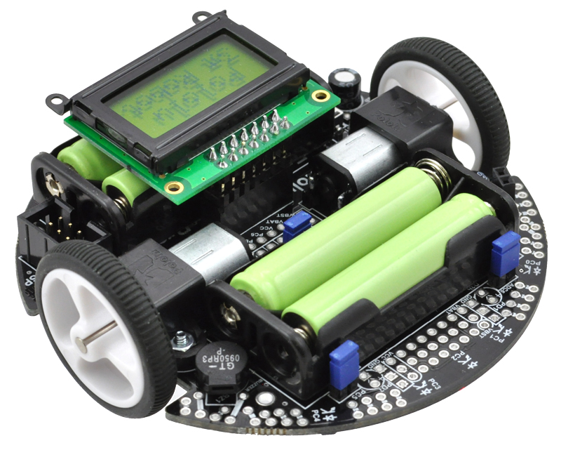 |
| Pololu 3pi robot. |
|---|
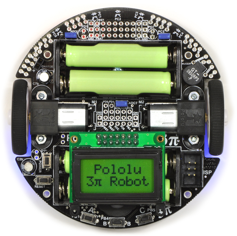 |
| Pololu 3pi robot, top view. |
|---|
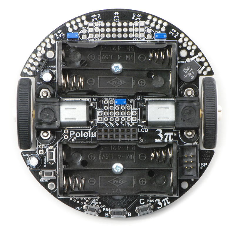 |
| Top view of the Pololu 3pi robot without batteries or LCD. |
|---|
 |
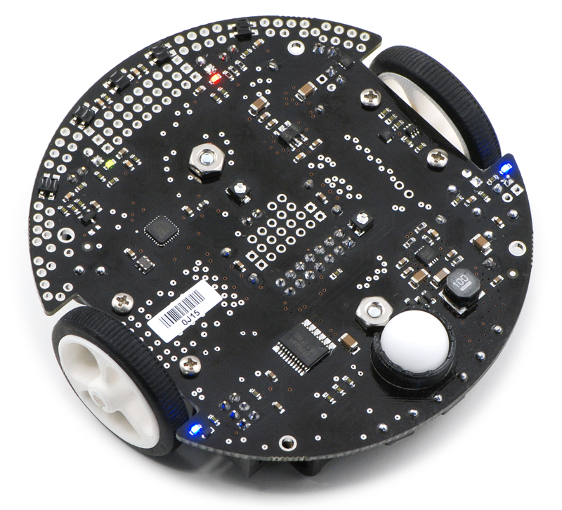
| Pololu 3pi robot, bottom view. |
|---|
 |
| Pololu 3pi robot, bottom view. |
|---|
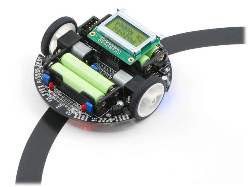 |
| Pololu 3pi robot on a 3/4″ black line. |
|---|
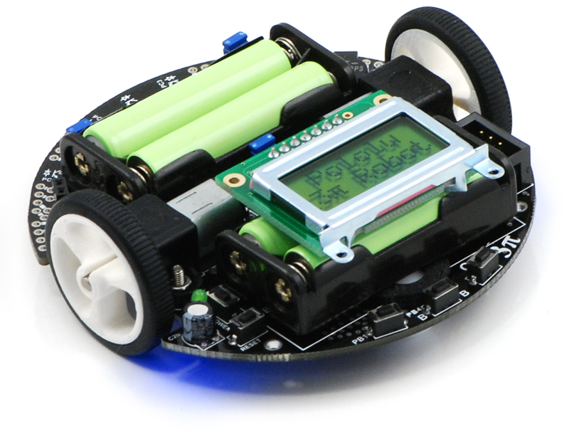 |
| Pololu 3pi robot. |
|---|
|
| Pololu 3pi robot on a 3/4″ black line. |
|---|
 |
| Pololu 3pi robots. |
|---|
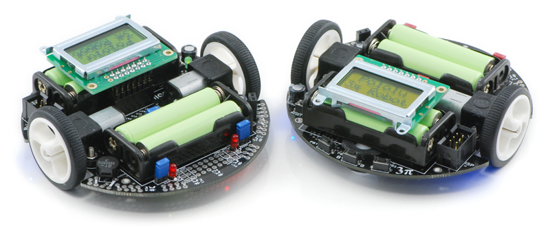 |
| Pololu 3pi robots. |
|---|
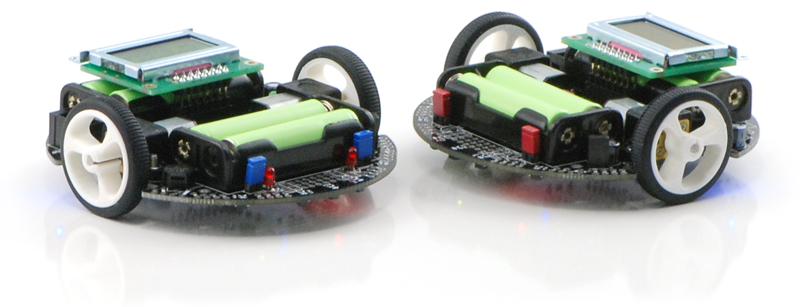 |
| Pololu 3pi robots. |
|---|
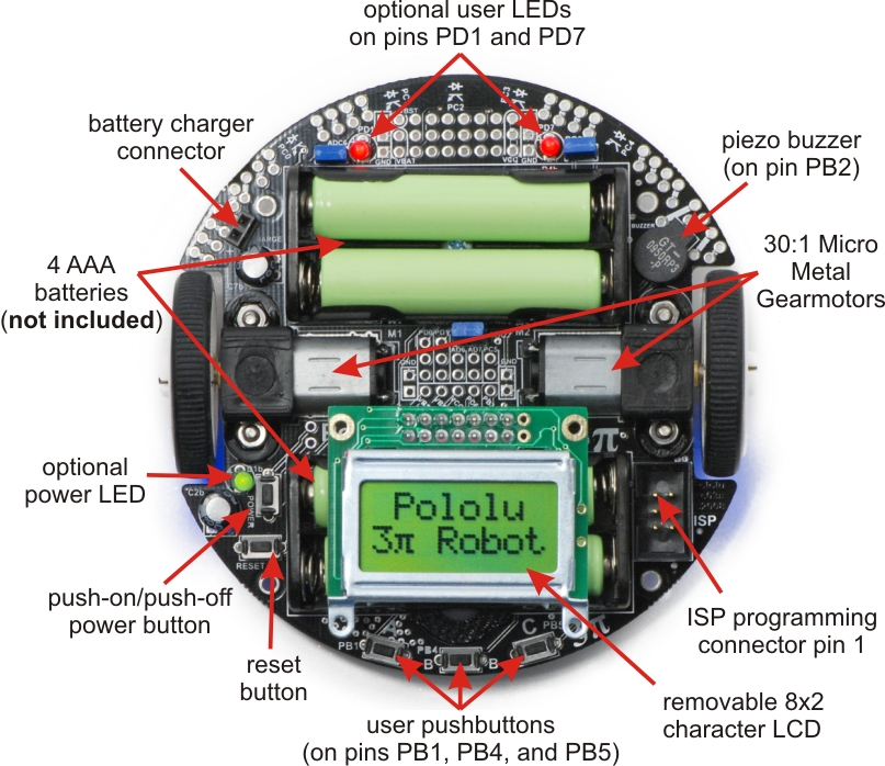 |
| General features of the Pololu 3pi robot, top view. |
|---|
 |
| Specific features of the Pololu 3pi robot, top view. |
|---|
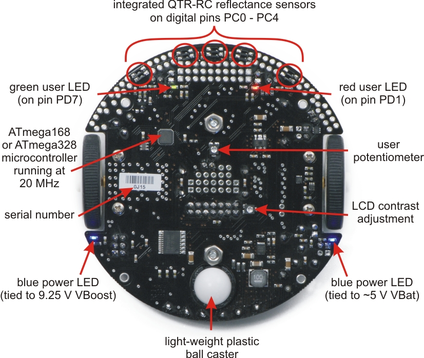 |
| Labeled bottom view of the Pololu 3pi robot. |
|---|
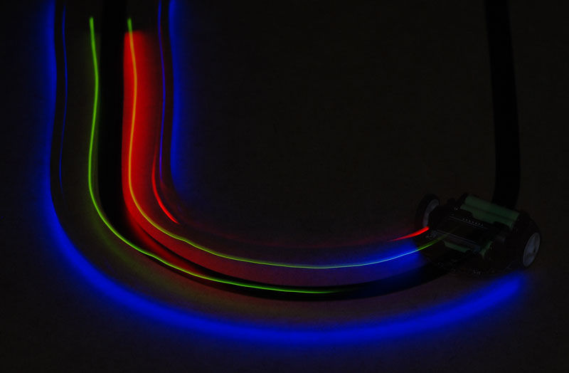 |
| A 3pi robot following a line in the dark, making the glow of the LEDs more apparent. |
|---|
 |
| A 3pi robot spinning in place in the dark after losing the line. |
|---|
 |
| Pololu 3pi robot simplified schematic diagram. |
|---|
Documentation and other information
 Pololu 3pi Robot User’s Guide (Printable PDF)User’s guide for the Pololu 3pi Robot.
 Pololu AVR Programming Quick Start Guide (Printable PDF)This guide explains how to get started programming your Orangutan or 3pi Robot in Windows, Linux or Mac OS X. It covers setting up an AVR development environment (Atmel Studio for Windows users), installing the Pololu AVR C/C++ Library, and setting up the Pololu USB AVR Programmer.
 Pololu AVR C/C++ Library User’s Guide (Printable PDF)Information about installing and using the C/C++ libraries provided for use with Pololu products.
 Pololu AVR Library Command Reference (Printable PDF)A reference to commands provided in the Pololu C/C++ and Arduino libraries for the AVR.
 Building Line Following and Line Maze Courses (Printable PDF)Step-by-step instructions for building your own line-following courses.
Programming Orangutans and the 3pi Robot from AVR Studio 4Guide for programming Orangutans and the 3pi robot from the Atmel’s older AVR Studio 4 IDE. It covers installing the Pololu AVR C/C++ Library, and setting up the Pololu USB AVR Programmer.
 Programming Orangutans and the 3pi Robot from the Arduino Environment (Printable PDF)Guide to making the Arduino IDE compatible with the 3pi robot and the Orangutan SV-328, Orangutan LV-168, and Baby Orangutan B robot controllers, including Arduino libraries for interfacing with all of their on-board hardware.
 Sample Project: 3pi Wall Follower (Printable PDF)Sample robot project for enhancing a 3pi robot to drive around objects on its left.
 Sample Project: RC 3pi (Printable PDF)Sample robot project for making the 3pi radio controlled.
 Application Note: Using the Motor Driver on the 3pi Robot and Orangutan Robot Controllers (Printable PDF)Detailed information about the 3pi Robot, Orangutan SV-328/168 and LV-168, and Baby Orangutan B motor drivers, including truth tables and sample code.
 3pi Robot VideosVarious videos of the Pololu 3pi robot in action.
File downloads
- 3pi quick-start sheet and schematic (486k pdf)
- A print-out of this quick-start sheet is included in with each shipped 3pi robot.
- 3pi simplified schematic diagram (481k pdf)
- Pololu 3pi Robot guia de usuario (3MB pdf)
- A Spanish version of our Pololu 3pi robot’s user’s guide provided by customer Jaume B, updated Nov 16, 2009.
- Line Maze Algorithm Presentation (505k pdf)
- A detailed presentation on teaching a robot to solve a non-looped line maze written by customer (and robotics professor) R. Vannoy. This can help you to better understand how to solve a line maze with your 3pi or custom maze-solving robot.
- 3pi main board drill guide (220k dxf)
- This DXF drawing shows the locations of all of the board’s holes.
Recommended links
- Pololu 3pi Forum Section
- The 3pi discussion section of the Pololu Robotics Forum.
- Tabletop Robotics 3pi Projects
- A series of interesting, customer-created open source projects for the 3pi robot, including barcode reading, grid navigation, and remote control.
- Simple 3pi Projects for the Arduino IDE
- These customer-written projects are intended to introduce the novice user to all the components on the 3pi robot and how they can be used while programming with the Arduino IDE. Each project builds on the one before it and comments within the programs are used to provide background information when new items are introduced. By Daniel J. Sullivan, August 2011.
- ATmega328P documentation
- Atmel’s product page for the ATmega328P.
- AVR Libc Home Page
- The web site for AVR Libc, which is the standard library of functions that you can use with C and C++ on the AVR.
- AVR Freaks
- AVR community with forums, projects, and AVR news.
- GCC, the GNU Compiler Collection
- Documentation for GCC, including the AVR GCC C/C++ compilers.
- WinAVR
- A free, open-source suite of development tools for the AVR family of microcontrollers, including the GNU GCC compiler for C/C++.
- AVR Studio 4
- The older version of Atmel’s free integrated development environment (IDE) for AVRs, which is no longer supported by Atmel.
- Anibit graphical programming tool for the Pololu 3pi
- This tool, which was made by Anibit, one of our distributors, provides a graphical programming environment for the 3pi robot which runs inside a web browser. The graphical code is converted to Arduino C++ code, which you can then copy and paste into the Arduino IDE. To use this tool, you will need to set up the Arduino IDE for programming the 3pi.
- Pololu 3pi: the 10,000 Mile Review
- Review of the 3pi robot written by R. Steven Rainwater, founding editor of Robots.net.
- Tutorial: AVR Programming on the Mac
- Customer Michael Shimniok has written a guide to programming AVRs (the Orangutan LV-168, specifically) using the Mac.
- Otimização Do Algoritmo De Maze Solver Para O Robô Pololu 3pi
- A paper (in Portuguese) describing the Pololu 3pi robot in general, and, specifically, how to write optimized maze solving code. By Ana Paula, December 2010.
- Home-made m3pi robot controlled by Bluetooth keyboard
- An mbed notebook (in Japanese) showing a 3pi robot with an ARM mbed controlled by Bluetooth keyboard. By Kazuhiro Ouchi, December 2010.
How do you pronounce “3pi”, anyway?The “pi” in 3pi is pronounced like the greek letter π (e.g. three-pie). The name comes from the size of the robot’s chassis, which is approximately 3pi centimeters (9.4 cm, 3.7″in) in diameter.How does the battery charger connection work? Is there a charger included?The 3pi robot does not include batteries or a charger. The battery charger connection provides a direct connection to the batteries so that if you use rechargeable batteries, you can recharge them without taking them out of the robot. You will need a charger capable of charging four NiMH or NiCD cells (depending on what you’re using) in series. Such chargers are readily available in hobby stores for charging electric model airplane battery packs. Please note that rechargeable batteries are not required as the 3pi can use regular alkaline cells, but we strongly recommend investing in some NiMH cells and a charger.I’m ready to order a 3pi, but am wondering what sort of battery charger I need. Any recommendations?
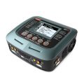
You will only need a battery charger if you plan on powering your 3pi with rechargeable cells. You want a charger that can work with 4 NiMH cells in series (they are usually in battery packs, not in battery holders like on the 3pi) and can be powered by AC (a wall outlet). In general, having more flexibility (such as the ability to charge 1-8 cells) is nice for future projects. We regularly use the iMAX-B6AC balance charger/discharger for charging batteries here at Pololu.
Chargers like the iMAX-B6AC can be connected to the 3pi’s battery charge port, allowing you to charge the batteries while they are still in the robot.
Since the 3pi just uses ordinary AAA batteries, you can also use AAA chargers (into which you stick the individual cells) available at most general electronics stores. For example, a quick Google search yields:
4 AA & 4 AAA Ni-MH Battery Charger
(Note that we have no experience with this particular charger and are not specifically endorsing it.) The downside to a charger like this is that you have to remove the batteries from the 3pi to charge them.
The green (PD7) user LED on my 3pi flickers even though I’m not doing anything with it. Is it malfunctioning?No, this behavior is normal. To get the most out of the ATmega168’s I/O lines, one of the LCD’s data lines (PD7) doubles as the control line for the green LED, so this LED might flicker when the LCD is updated. As such, the amount of flickering and effective brightness of the LED will generally be a function of the rate at which you are updating the LCD. Note that you can change the state of the green LED without affecting the LCD at all, and using the LCD via the Pololu AVR library will only very briefly change the state of the LED line as needed before restoring it to its previous state.Can I augment/customize my 3pi by adding my own electronics/sensors?Yes. The easiest way to augment your 3pi is through an expansion kit, which can comes either with cutouts that let you see the LCD below or without cutouts. The version without cutouts replaces the LCD, giving you access to more I/O lines and more prototyping space. An expansion kit is not required for addition of your own electronics, however.
The 3pi robot has a limited number of free I/O lines that can be used as inputs for additional sensors or to control additional electronics such as LEDs or servos. Please see section 10.c of the 3pi user’s guide for more information.
Are wheel encoders included or can they be added to the 3pi robot? Are there sufficient I/O lines available for encoders?Unfortunately, there is no provision for encoders on the 3pi: we do not have any sensor solution and the microcontroller does not have enough I/O lines. Therefore, the only way to add encoding is to make your own sensor setup and to use an external microcontroller (for example, on an expansion PCB) to do the sensor reading. The secondary microcontroller can communicate with the main 3pi controller using the asynchronous serial lines, which are available for expansion purposes.I’m adding peripherals to the 3pi that require 5 V. How much current can the 5 V (Vcc) power bus supply?Because the 5 V goes through two power stages, the answer is not completely clear-cut. The 5 V regulator itself has a 900 mW power dissipation limit, so with a 4.3 V drop from the 9.3 V boost voltage to 5 V, we get just over 200 mA. The stock electronics on the 3pi typically use under 50 mA (however, this depends on what your program is doing, if you are making high-frequency noise with the buzzer, and so on), so you could figure an absolute max of 150 mA, with 100 mA being a more comfortable guideline.
However, the boost voltage has a limit of its own of around 1 A, which is dependent on your battery voltage. The motors and IR LEDs also use this supply, so using a lot for your 5 V will affect what is available for the motors. You can almost stall the motors and still have the full boost voltage on the motors in the stock configuration; if you’re also drawing an extra 200 mA for other electronics, the boost voltage will start dropping as the motors approach stall, though this is not necessarily a bad thing since it will limit the stress on the motors and lower the voltage drop on the linear regulator.
What is the purpose of the small piece of electrical tape stuck on the bottom of the 3pi PCB near the ball caster? Can I remove it?The electrical tape provides extra protection for the boost regulator circuit. It is easy to touch this area of the PCB with your finger when pushing the power or reset button, and without the tape your finger can change the boost voltage to levels that are out of spec for components on the board. We do not recommend that you remove it.


There are no reviews yet.